 Redline
Generated project tables
Put a sheet list, equipment index, or cable schedule on the drawing. Generated tables read live project information: changing a device ID, page title, or cable measurement updates the rows without maintaining a second list.
Create and edit a table
With nothing selected, choose Insert table in the sidebar, or use a preset: Insert Table: Frontmatter, Device occurrence index, or Cable schedule. Place the frame on the canvas, then select it to configure it in Inspector. These insertion choices are also in the Edit menu.
Edit the caption, position, size, fonts, and row spacing on the selected frame. The table font controls affect the caption, headings, and cells together; reset them to inherit the project font again. Preserve newlines keeps line breaks from the source text instead of replacing them with spaces.
Cells are generated, not directly editable. Change the devices, cables, or pages they describe, on the canvas or through Summary: Nodes. Summary: Annotations helps locate placed tables by their caption text.
Choose the rows and columns
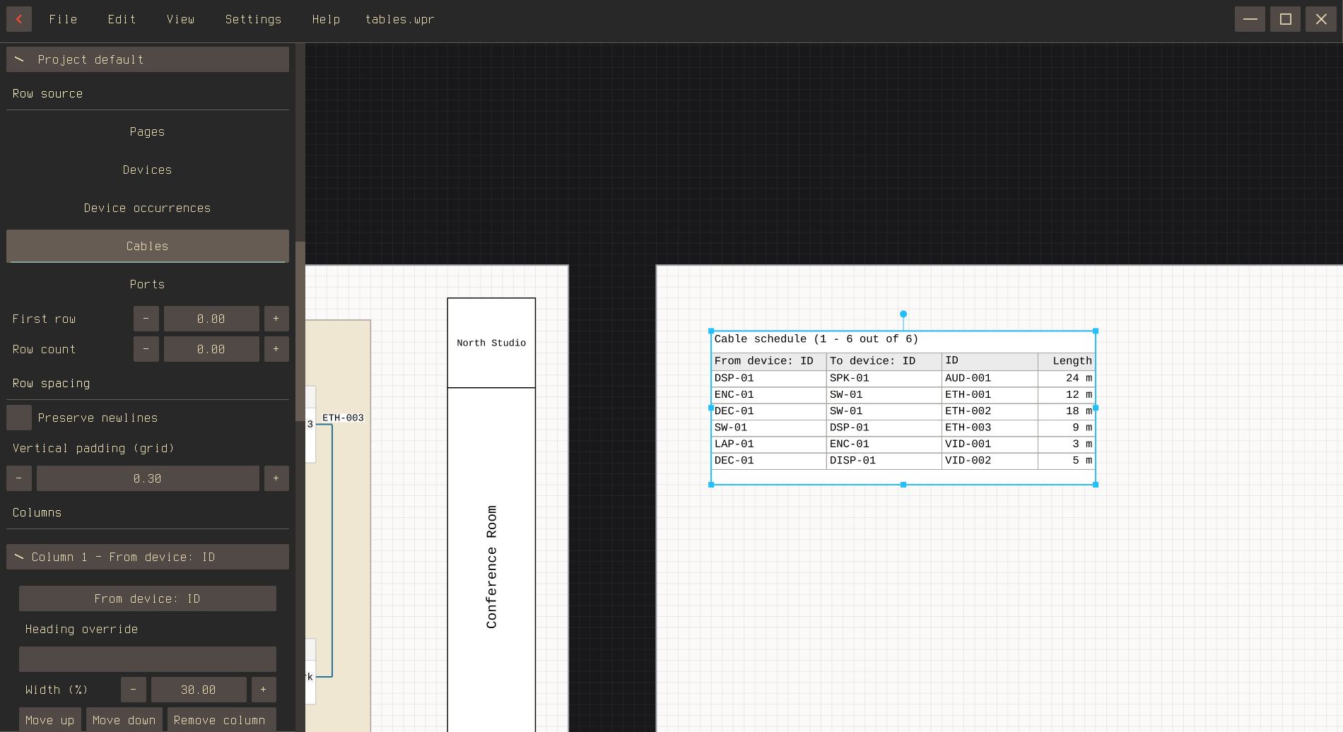
Row source determines what one row represents:
- Pages: one row per sheet.
- Devices: one row per physical device.
- Device occurrences: one row per drawn view of a device.
- Cables: one row per physical cable.
- Ports: one row per physical connector, including unused connectors.
Repeated views do not add extra physical devices, cables, or ports. Changing the row source resets columns, sorting, and the starting row.
For each column, choose its field, optionally replace its heading, set its share of the table width, and choose left, center, or right alignment. Presets provide starting settings; alignment stays editable regardless of the field. Width weights are proportional: 2 gives twice the width of 1. They do not need to total 100, and changing one does not rewrite the others. Add, remove, or move columns to arrange them; reset columns restores the source's defaults and clears sorting. Available fields include IDs, labels, subtext, user fields, and related page information. Cable columns can also read either endpoint's device and port details; port columns can read their device's details.
An equipment list with manual links
Select a device and open Metadata, then User fields in Inspector. Choose Add field. Set Key to Manual URL and Value to the manual's web address. These values belong to the physical device, so its other views share them.
Insert a table and set Row source to Devices. Keep ID and Label, remove Pages, then add a column and choose the Manual URL user field. If it is not listed yet, choose User field and enter Manual URL as its Field key. The key must match the device's field exactly; devices without that field have a blank cell. This produces one row per device with its ID, name, and manual address.
Sheet lists
The Frontmatter preset starts with page titles and IDs in document order. Columns can also show text fields from the page's frontmatter, including local overrides and generated values.
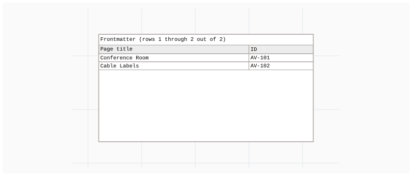
See Frontmatter and title blocks for those fields.
Device occurrence indexes
The device occurrence preset shows device IDs, occurrence numbers, and pages. Here, SW-01 appears twice: 1/2 and 2/2 are two views of the same switch. Occurrence numbers follow the saved order of those views, not page order.
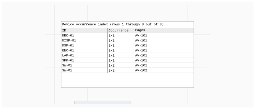
Related pages follow document order, with duplicate and empty values omitted. The Pages column uses a page's title when it has no ID. A view overlapping several pages can list them all.
Cable schedules
The cable schedule preset shows source device, destination device, cable ID, and recorded length. Each physical cable appears once, even with repeated drawings. Unused ports and number reservations are excluded.
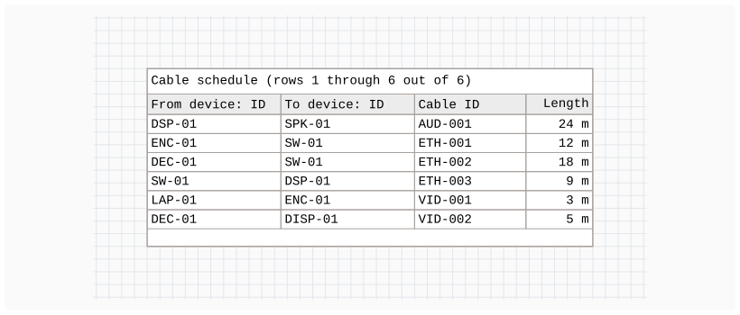
Add a Pages column to list the sheets containing any view of the cable, including its endpoints, route, or flags. Length is an installation measurement, not the length of the drawn line. Edit it through Edge lengths.
Sort and fit the rows
Use source order, or add sort levels for your chosen columns. Each level can be ascending or descending; earlier levels take priority. Lengths sort by physical measurement, even when their units differ. Sorting changes this table, not page order, device occurrence order, cable IDs, or the numbering sequence.
For First row, enter 0 to start at the first row, or 2 to start at the third. Row count limits the rows shown; 0 means no explicit limit. Sorting happens before this range is selected. The frame still limits what fits: wrapped text, font size, and row padding all affect its capacity.
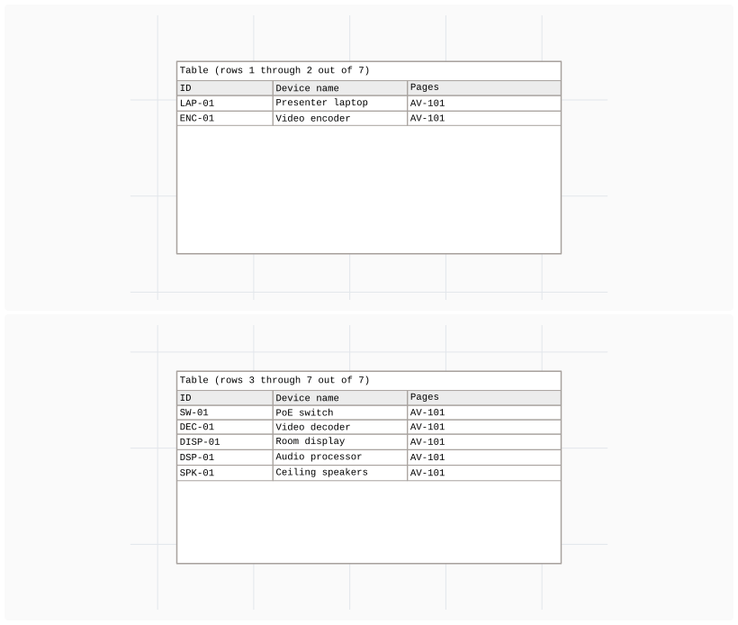
The caption reports the visible range and total rows. To continue after rows 1–2, duplicate the frame onto another sheet and set First row to 2. Keep the same columns and sorting. Frames do not flow automatically; changed content or frame sizes can leave gaps or repeated rows between them.
Export the drawing or the data
Drawing exports include the table as placed, with its frame and row range. See Exporting the document for output formats.
For spreadsheet data, choose Export table... in the selected table's Inspector or the File menu. Choose a placed table, then use Export CSV... to save it. The CSV includes headings and every live row, with the configured columns and sorting. It ignores frame size, First row, and Row count, and contains plain text rather than the caption or rich-text formatting.