 Redline
Devices and ports
A node is one view of a device on the drawing. Show the same device on different sheets without counting it twice in the equipment inventory.
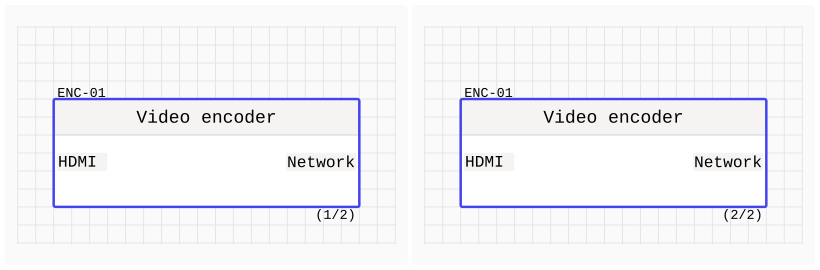
Views of the same device share labels, IDs, subtext, and user fields. Each view has its own position, size, and port layout. Matching IDs alone do not link two devices.
To place another view, select the device in Inspector, choose Add another view, then place the preview on the canvas. Copying and pasting a device instead creates a separate device with its own information.
Summary: Nodes lists devices and their views. See Summary: Nodes for finding and ordering them.
Ports
A port is a connection point on the left or right of a node. Connect two ports to draw a cable between them.
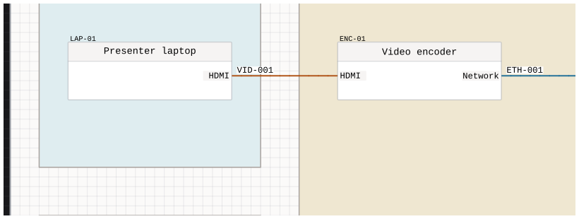
Create ports in a device draft or add them to an existing node in Inspector. In a draft, you can enter several port labels, one per line. Select a port to edit its details or change its position.
Port positions on the drawing are separate from the physical order used for Summary: Edge.
Device information
Select a node to edit its label, ID, subtext, or user fields in the inspector. For several devices at once, use Summary.
User fields are named values you add yourself, such as Location or Manual URL. They can also become columns in Generated project tables, so information attached to equipment can appear on the sheet without being typed out again.